PAL video output from a TI-83 Plus
Posted: Wed 14 Nov, 2007 3:06 pm
(This is a copy of a journal post).
My work with the VDP in the Sega Master System made me more aware of how video signals are generated, so thought it would be an interesting exercise to try and generate them in software. This also gives me a chance to test Brass 3, by actively developing experimental programs.
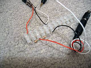
I'm using a simple 2-bit DAC based on a voltage divider, using the values listed here. This way I can generate 0V (sync), ~0.3V (black), ~0.6V (grey) and 1V (white).
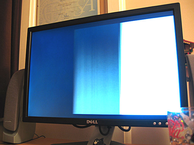
My first test was to output a horizontal sync pulse followed by black, grey, then white, counting clock cycles (based on a 6MHz CPU clock). That's 6 clock cycles per µs.
The fastest way to output data to hardware ports on the Z80 is the outi instruction, which loads a value from the address pointed to by hl, increments hl, decrements b and outputs the value to port c. This takes a rather whopping 16 clock cycles (directly outputting to an immediate port address takes 11 clock cycles, but the overhead comes from loading an immediate value into a which takes a further 7). The time spent creating the picture in PAL is 52µs, which is 312 clock cycles. That's 19.5 outi instructions, and by the time you've factored in the loop overhead that gives you a safe 18 pixel horizontal resolution - which is pretty terrible.
Even with this technique, in the best case scenario you output once every 16 clock cycles which gives you a maximum time resolution of 2.67µs. This is indeed a problem as vertical sync is achieved by transmitting two different types of sync pulse, made of either a 2µs sync followed by 30µs black (short) or 30µs sync followed by 2µs black (long). In my case I plumped for the easiest to time 4µs/28µs and hoped it would work.
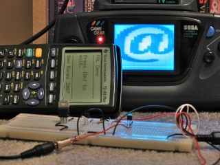
Anyhow, I made a small three-colour image for testing:
Of course, as I need to output each scanline anyway I end up with a resolution of 304 lines, which gives me rather irregular pixels, so I just stretch the above image up to 20×304. Eagle-eyed readers would have noticed that the horizontal resolution is only 18 pixels, but somewhere in the development process I forgot how to count and so made the image two pixels too wide.

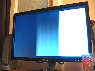
As you can see, it shows (the entire image is shunted to the right). TVs crop the first and last few scanlines (they aren't wasted, though, and can be used for Teletext) so that's why that's missing. A widescreen monitor doesn't help the already heavily distorted pixels either, but it does (somewhat surprisingly) work.
With a TI-83+ SE (or higher) you have access to a much faster CPU (15MHz) and more accurate timing (crystal timers rather than an RC circuit that changes speed based on battery levels) as well as better interrupt control, so on an SE calculator you could get at least double the horizontal resolution and output correct vertical sync patterns. You also have better control over the timer interrupts, so you could probably drive hsync via a fixed interrupt, leaving you space to insert a game (the only code I had space for checks to see if the On key is held so you can quit the program - more clock cycle counting). I only have the old 6MHz calculator, though, so I'm pleased enough that it works at all, even if the results are useless!
My work with the VDP in the Sega Master System made me more aware of how video signals are generated, so thought it would be an interesting exercise to try and generate them in software. This also gives me a chance to test Brass 3, by actively developing experimental programs.
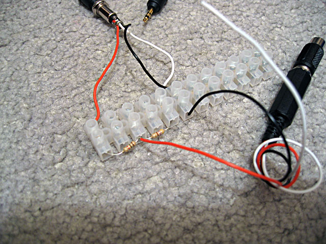
I'm using a simple 2-bit DAC based on a voltage divider, using the values listed here. This way I can generate 0V (sync), ~0.3V (black), ~0.6V (grey) and 1V (white).
My first test was to output a horizontal sync pulse followed by black, grey, then white, counting clock cycles (based on a 6MHz CPU clock). That's 6 clock cycles per µs.
The fastest way to output data to hardware ports on the Z80 is the outi instruction, which loads a value from the address pointed to by hl, increments hl, decrements b and outputs the value to port c. This takes a rather whopping 16 clock cycles (directly outputting to an immediate port address takes 11 clock cycles, but the overhead comes from loading an immediate value into a which takes a further 7). The time spent creating the picture in PAL is 52µs, which is 312 clock cycles. That's 19.5 outi instructions, and by the time you've factored in the loop overhead that gives you a safe 18 pixel horizontal resolution - which is pretty terrible.
Even with this technique, in the best case scenario you output once every 16 clock cycles which gives you a maximum time resolution of 2.67µs. This is indeed a problem as vertical sync is achieved by transmitting two different types of sync pulse, made of either a 2µs sync followed by 30µs black (short) or 30µs sync followed by 2µs black (long). In my case I plumped for the easiest to time 4µs/28µs and hoped it would work.
Anyhow, I made a small three-colour image for testing:
Of course, as I need to output each scanline anyway I end up with a resolution of 304 lines, which gives me rather irregular pixels, so I just stretch the above image up to 20×304. Eagle-eyed readers would have noticed that the horizontal resolution is only 18 pixels, but somewhere in the development process I forgot how to count and so made the image two pixels too wide.
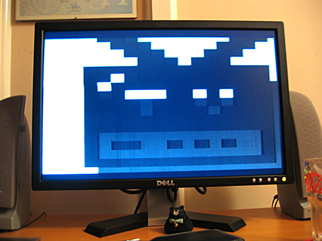
As you can see, it shows (the entire image is shunted to the right). TVs crop the first and last few scanlines (they aren't wasted, though, and can be used for Teletext) so that's why that's missing.
With a TI-83+ SE (or higher) you have access to a much faster CPU (15MHz) and more accurate timing (crystal timers rather than an RC circuit that changes speed based on battery levels) as well as better interrupt control, so on an SE calculator you could get at least double the horizontal resolution and output correct vertical sync patterns. You also have better control over the timer interrupts, so you could probably drive hsync via a fixed interrupt, leaving you space to insert a game (the only code I had space for checks to see if the On key is held so you can quit the program - more clock cycle counting). I only have the old 6MHz calculator, though, so I'm pleased enough that it works at all, even if the results are useless!